Propagation of Radio Waves and Antenna Construction
Since then further notes appeared in RSGB. The minimum frequency that will penetrate the ionosphere at vertical incidence.

Ionospheric Radio Wave Propagation Above The Critical Frequency Results Download Scientific Diagram
Responsible for reflection of HF radio waves.

. Master of Science Engineering Technology December 2002 87 pp 7 tables 12 illustrations. Since the propagation characteristics depend on frequency several key frequencies can de defined. However in the present day and age thanks to many commercially manufactured EFHW antenna available in the market more and more radio amateurs especially the newcomers to HF communication are opting for this antenna despite its numerous shortcomings that can only be partially mitigated to acceptable levels by careful adjustments and tweaks that could.
The design was originally devised in 1946 but it was not until 1958 that it was published when it appeared in the July 1958 RSGB Bulletin the predecessor of the current RSGB RadCom journal. Radio waves from space were first detected by engineer Karl Guthe Jansky in 1932 at Bell Telephone Laboratories in Holmdel New Jersey using an antenna built to study radio receiver noise. The first purpose-built radio telescope was a 9-meter parabolic dish constructed by radio amateur Grote Reber in his back yard in Wheaton Illinois in 1937.
This effect is due to the spreading of the radio waves as they propagate and can be calculated by. A parabolic antenna is an antenna that uses a parabolic reflector a curved surface with the cross-sectional shape of a parabola to direct the radio waves to the receiver in its focal pointThe most common form is shaped like a dish and is popularly called a dish antenna or parabolic dishThe main advantage of a parabolic antenna is that it has high directivity. The sky survey he performed.
Antenna is reduced by a factor of four. Ryan Patrick L Radio frequency propagation differences through various transmissive materials. RADIO FREQUENCY PROPAGATION DIFFERENCES THROUGH VARIOUS TRANSMISSIVE MATERIALS Patrick L.
Thesis Prepared for the Degree of MASTER OF SCIENCE. The G5RV antenna is based upon the doublet antenna concept and it was designed by Louis Varney who held the amateur radio callsign G5RV. D the distance between receiver and transmitter λ free space wavelength cf c speed of light 3 x 10⁸ ms f frequency Hz Equation 3 above describes line-of-sight or free space.
At other angles the wave will be reflected back. The critical frequency increases during the daylight and decrease at night.
The Ionosphere And T Radio Wave Propagation Download Scientific Diagram

Pin On At Home
Bee 4433 Antenna Propagation Radio Propagation Ir Dr Nurul Hazlina Noordin

A Sketch Anomalous Long Distance Propagation Of Vhf Radio Waves For Download Scientific Diagram
1 4 Wave Aviation Band Ground Plane Antenna Ham Radio Ham Radio Antenna Shortwave Radio

G0ksc Simple To Build High Performance Yagi And Quad Antennas Home Of The Lfa Yagi Free Yagi Antenna Des Ham Radio Radio Communication Ham Radio Antenna

Pin On Ham Radio Antennas

Propagation Of Radiofrequency Waves In Space

From Wikiwand Vhf Ground Plane Antenna Ham Radio Antenna Ham Radio Radio

Fundamentals Of Radio Propagation Vu2nsb Com Amazing Amateur Radio

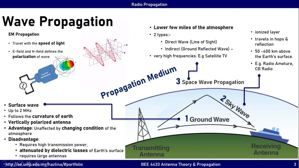
Electromagnetic Wave Propagation Ground Sky Space Wave Examples

Space Wave Propagation Download Scientific Diagram

Propagation Of Radio Waves

What Is Radio Propagation Rf Propagation Bug Out Bag Builder

136 To 174 Mhz Base Station Antennas Jpg Onde Radio Spectre Electromagnetique Onde Electromagnetique

Pin On Software

Line Artwork Four Common Types Of Antenna Compared Dipole Folded Dipole Reflector And Yagi Ham Radio Antennas Ham Radio Antenna

Propagation Path Of The Radio Wave From The Underground Sensor Node To Download Scientific Diagram
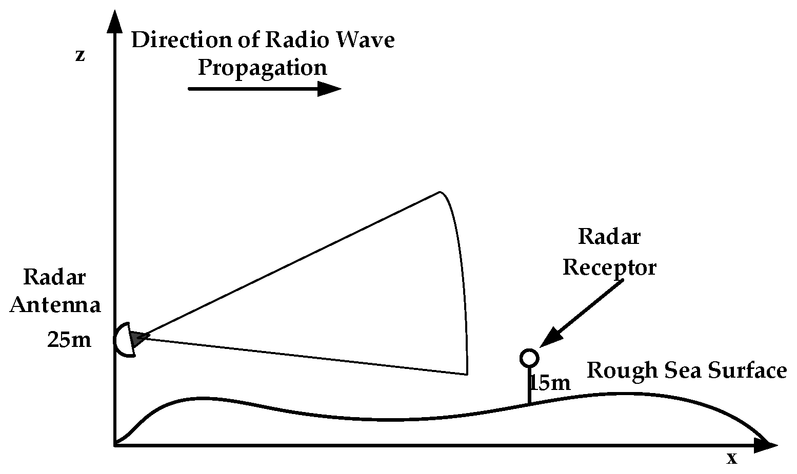
Sensors Free Full Text Parabolic Equation Modeling Of Electromagnetic Wave Propagation Over Rough Sea Surfaces Html


Comments
Post a Comment